
ArduCalc Graphing
Arduino based RPN Graphing Calculator

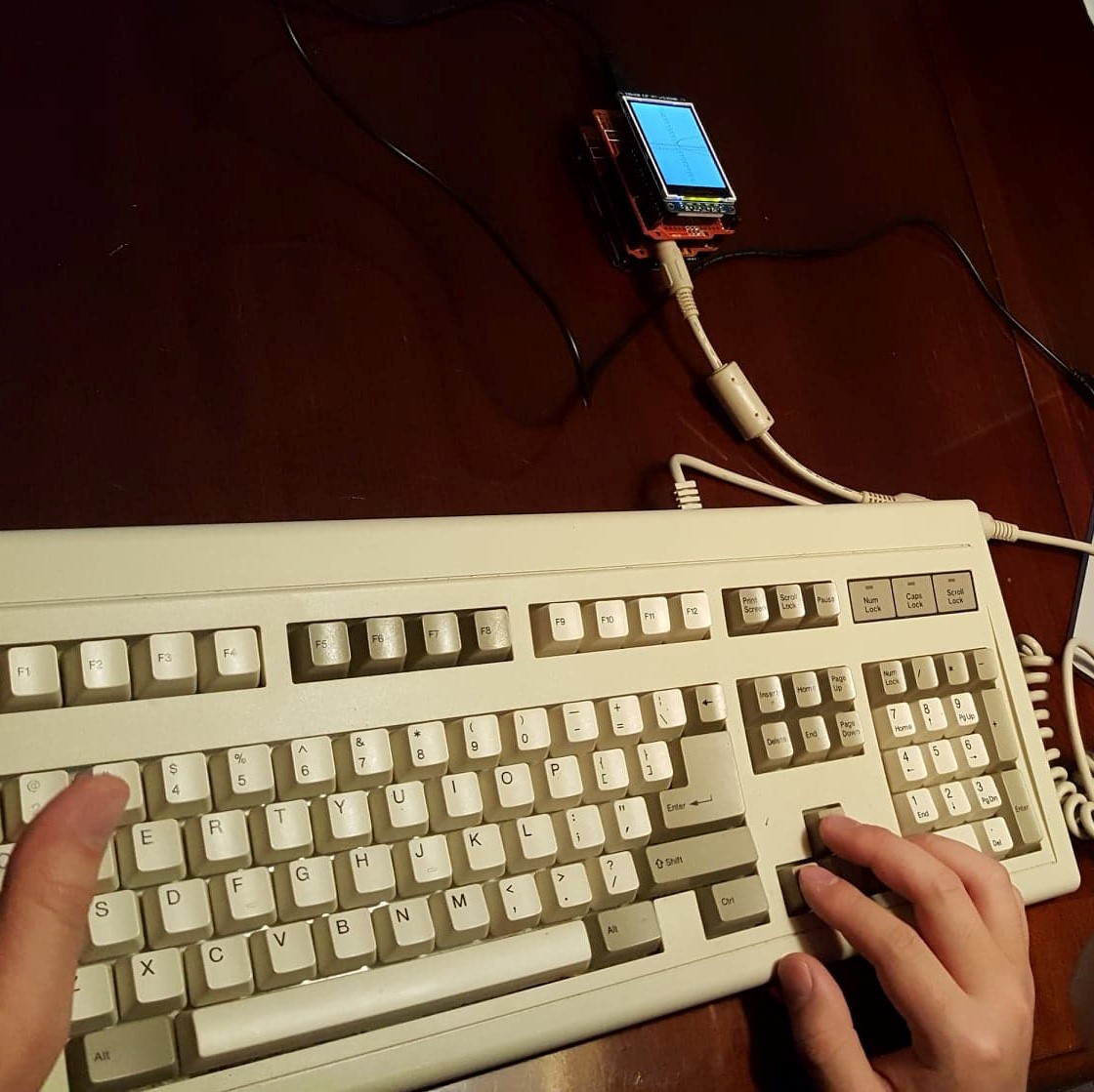
Apologies for the poor quality of the images – again I didn’t think of taking pictures of the calculator operation – and at the moment I don’t have a PS/2 keyboard to show off the functions.
This was my favorite class project yet – build anything you want using Arduino. So, I decided to build a stack based RPN graphing calculator. I’ve always admired the HP series of RPN calculators, like the legendary HP-35, the world’s first pocket calculator. Another reason to choose RPN was the programming ease – my parser didn’t have to understand the complexities of parenthesizes and algebraic notation. I wanted RPN, I wanted keyboard input, and I wanted a screen. I also wanted to write everything from scratch.
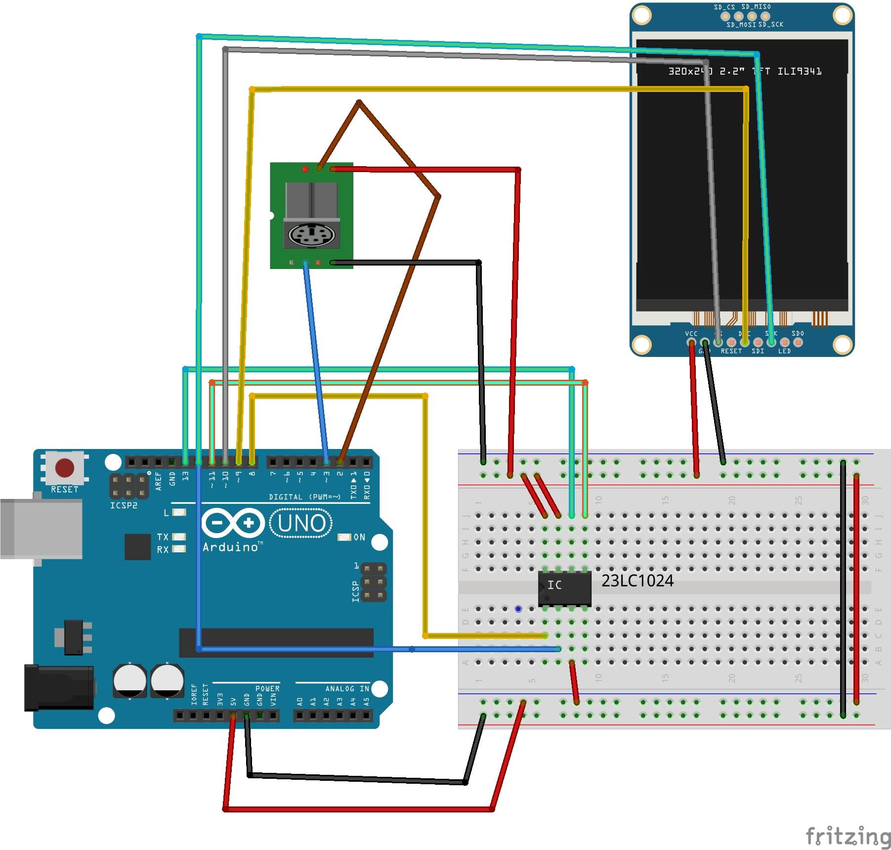
I first must stress just how much I dislike fritzing. I would never chose it voluntarily – I think it’s an ugly and inelegant way of representing things compared to the ease of a schematic. However, that was what we were supposed to use for the class, and so here it is.
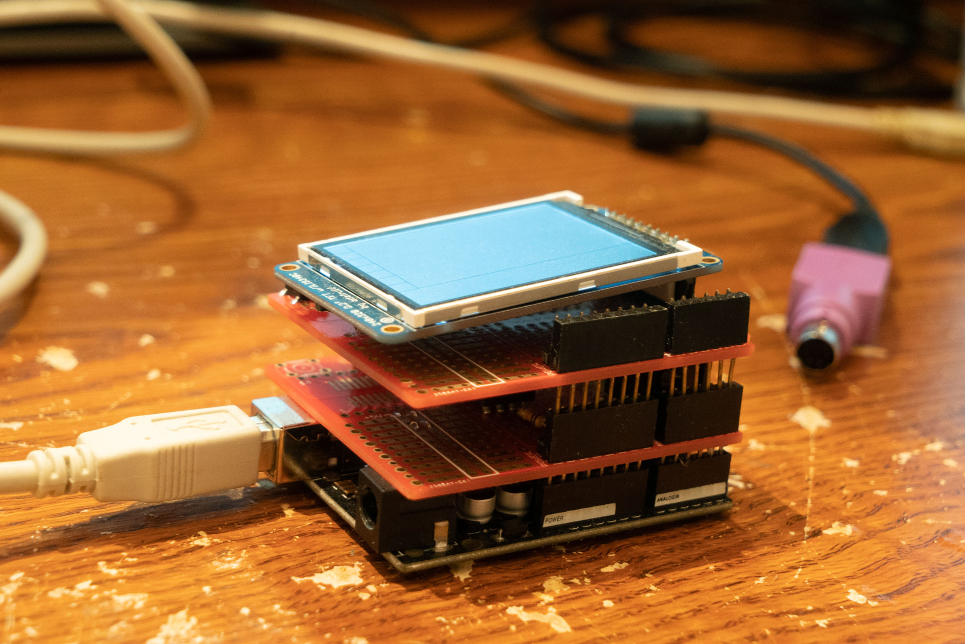
I decided that we would (my partner Andrew and I) have a color LCD screen, and we got a 320×240 job, which seemed like the minimum for a pleasant text and graphics display. The TI-84 is a disgrace for its terrible screen. (I’ve been a calculator enthusiast for a while, if you can tell) Of course, that means that when graphing, the pitiful 2k of ram inside the Arduino has no chance of storing the required data. So, we would need to increase the amount of RAM in an Arduino. I found a SPI SRAM job with 1Mb of memory. Now we had enough memory for graphics and even storage of previous data! For the keyboard I decided to go for PS/2 because it could directly interface with the Arduino, unlike USB, and it was cheap.
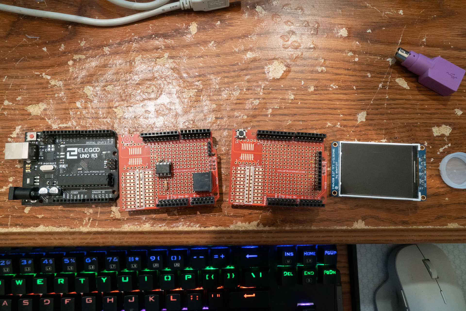
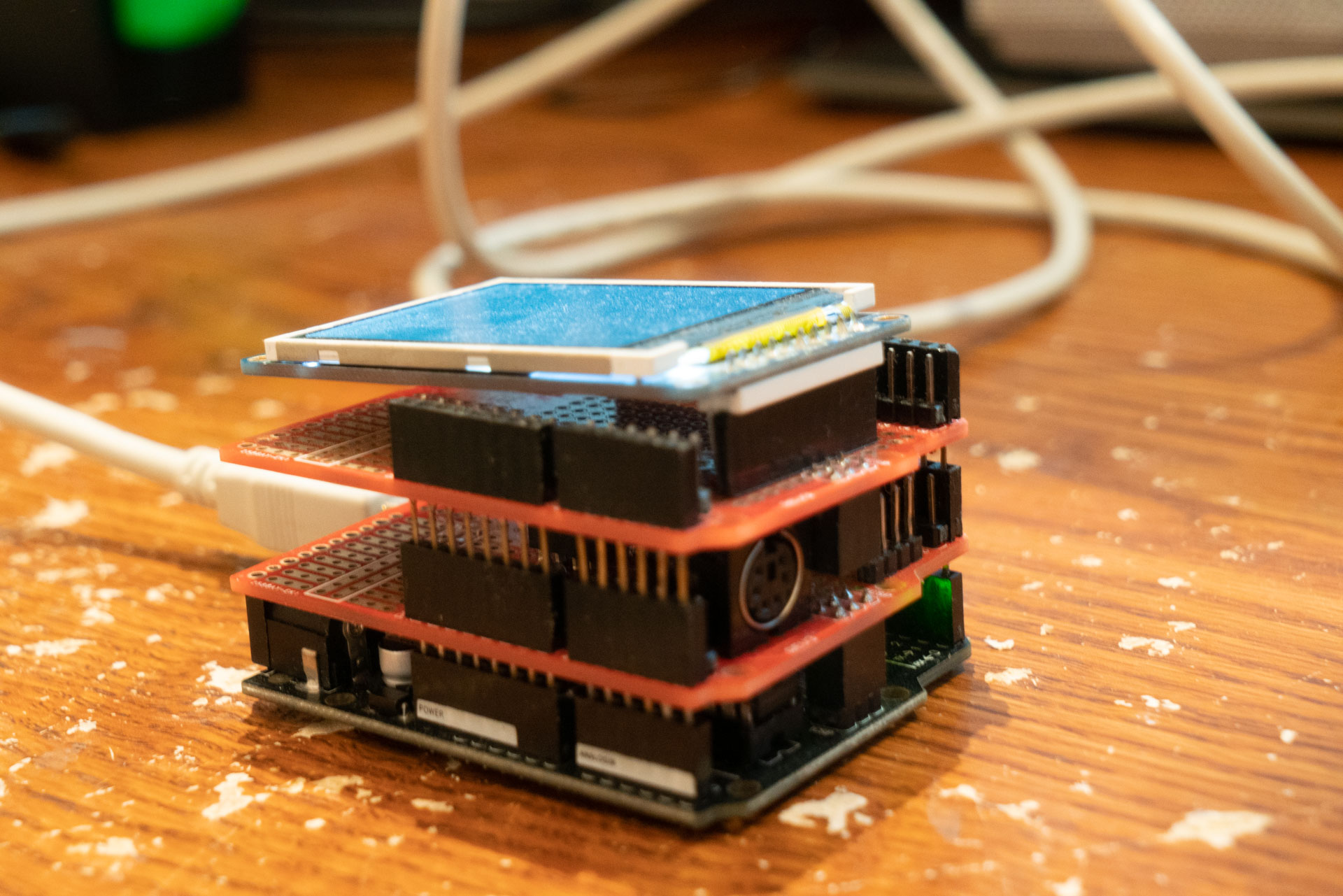
For the physical design, I built the SRAM and PS/2 on one Arduino shield, and made a socket for the LCD on another. They stack together. Unfortunately, the shields I bought were very cheap and reliability is, and always has been, poor.
For the programming, I wrote the parser, ALU, GUI, memory management, and the .main. Andrew wrote the CORDIC trig functions and the plotter. The plotter is just a function called by the ALU when it’s told to graph, but it does have smoothing functions and other nice features that you don’t see in these pictures, since they were taken before they were added.
Since WordPress doesn’t have support for .c and .h files, here’s a link to my cloud containing the code.
https://1drv.ms/f/s!AjCk2mjNF5oep-R_KB8kDfZrDQ4lyA
Here’s a short description of the functions of the code. We had to make a poster, so that’s where it comes from.
Calculator Operations
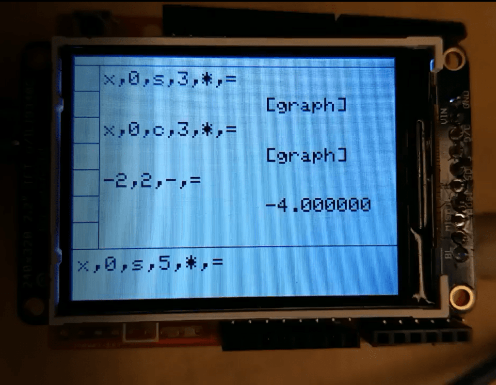
Users can input a series of mathematical operations. Inputs are parsed and ultimately pushed and stored on a local SRAM stack. Calculations are performed as inputs are read from the stack, and the results are displayed on screen.
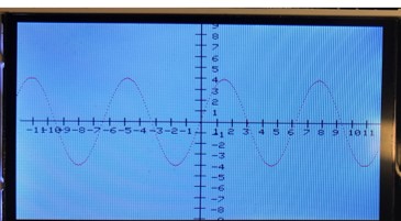
Equations are graphed by generating a Y value for each X value. (There are 320 pixels which represent X!). The results are stored on the individually addressable external SRAM chip. Address location data are stored in a data struct in local SRAM. The graphing function retrieves values from the SRAM as it plots each individual (X,Y).
The current implementation supports storing the address locations of three equation graphs in SRAM. Additional graphs will override prior address locations due to GUI limitations. Easily overcome, external SRAM could store more than 50 graphs.
Interrupt Driven Keyboard Input, Parsing, and ALU
The user inputs data using a PS/2 interface keyboard in Reverse Polish Notation (RPN)[3]. RPN and PS/2 were chosen due to their respective ease of arithmetic implementation and simplified interrupt driven protocol. Input is stored in a circular buffer connected to an editable WYSIWYG input display. After user input completion, the buffer array is pushed to a stack on the local SRAM. The parser pops out values, parses them into numbers and operators, and pushes them back.
The ALU then pops out three units at a time, two values and an operator, performs arithmetic, and pushes the answer back. This is repeated until the final answer is reached, where then the answer is written to the external SPI SRAM chip. In the case of graphing functions, the entire process is repeated for each X value.
GUI
The GUI presents users with the ability to observe real time inputs from the keyboard, and the ability to preserve equations and answers. The user can input calculations in a WYSIWYG cursor driven text box. After the calculation is performed, user data for that calculation is stored in a data struct, which stores the last three calculations. This is displayed on home and updated for new inputs. The user can also change graph settings via the GUI. Measures were left for history search and manipulation.
CORDIC Algorithm Implementation
The COordinate Rotational DIgital Computer algorithm is a particularly efficient algorithm for calculating approximate vector rotations and angles using digital logic.
The algorithm can be fully implemented using only bit shifts and addition / subtraction, making it incredibly efficient and practical for rapid real time calculations.
To perform a vector rotation, an initial vector with initial angle wi is rotated through a series of predetermined angle values, such that the final angle wf matches some input angle. Each iterative rotation transforms the resulting x and y component of the vector.
We implement the rotation mode of the algorithm to calculated cos(ω), sin(ω), and tan(ω).
Our implementation first determines the signs of the result, and then proceeds to execute the CORDIC algorithm to perform a vector rotation for a user stipulated angle.
Our implementation is more of an emulation: We perform bit shifts as a multiplication by a power of two, due to undefined behavior that arises when operating with floating point numbers on the Arduino platform.
