
Wireless Energy Transfer (L)
Inductive Wireless Energy


Credit to Marko of 4HV
My interest in high voltage and RF easily lead to an interest in wireless energy transfer, in addition to the rise of practical applications of wireless power when I was growing up, such as the rise of Qi and demos like MIT WiTricity. One of the neat demo items I made was this Inductive wireless energy transfer unit, based off the ideas of Marko on 4HV, who based his ideas off the ZVS flyback driver. I later took the ZVS flyback driver to make my own induction heater – but that’s a different post.

Remarks on circuit
This project uses a modified Royer oscillator, which is a relaxation oscillator with push pull transistors. I explain the circuit’s theory on my induction heater page, which uses a ZVS driver that operates the same as the Royer oscillator. To summarize, one of the transistors will turn on first, which will cause one leg of the inductor to be at ground potential. The other transistor will have a diode connected from its gate to that ground potential leg, which discharges that transistor’s gate to ground. Since the inductor forms an LC circuit, the tank current will be sinusoidal. At zero volts crossing, or where the tank voltage is at zero and just about to reverse in polarity, the transistor that is currently on will have its own gate discharge due to the same principal, as now the other leg of the inductor is at ground, and the cycle will continue with the previously off transistor.
In the original circuit, instead of a LC tank, an iron core transformer is used. This core will eventually saturated, drop to zero, and then reverse polarities. To modify the oscillator for use in wireless energy transmission, the transformer is replaced with an LC tank circuit, thus creating sine waves instead of square waves.


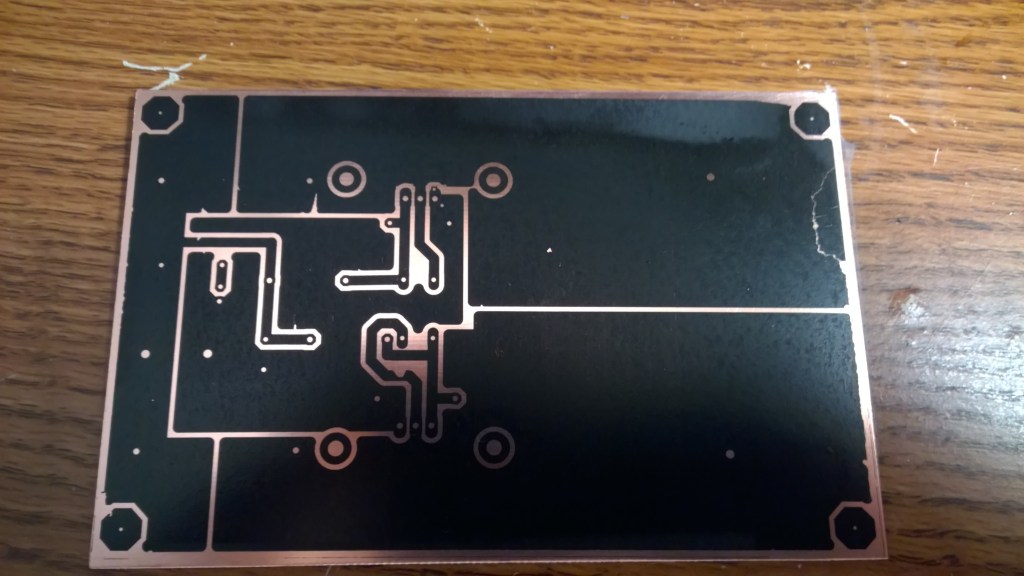


Since this is an RF device, (1.26Mhz, if you looked closely at the opening image) it had to be a PCB design. Luckily, since it was such a simple circuit, I didn’t have to worry too much about making errors in my design. As I’ve written about elsewhere on this site, I lost a lot of my files over the years, so I no longer have the board files. But, you can get a good sense of the layout from these pictures. I used mostly ground pours and shapes to make my traces, trying to practice good RF design. I think the end result was reasonable.
This was before the rise of cheap Chinese PCB services, so I was still making my own boards using the toner transfer process. You can look up the finer details, but in essence one uses a laminating machine and a laser printer to cover a bare PCB with plastic toner in the shape of the desired artwork. The toner doesn’t stick perfectly, so there are several tricks you can use, such as special rice covered paper and films to strengthen the black toner. (the green stuff) Anyway, once that step is complete, simply dunk the board in a solution of 2 parts H2O2 to 1 part HCL for 10min. Ferric chloride could also be used, but is in general horrible stuff. As you can see, the bare copper dissolves away, and you’re left with the copper below the toner. The toner is wiped away with acetone, and you have your board. The silkscreen is simply the same process stopped at the toner step.

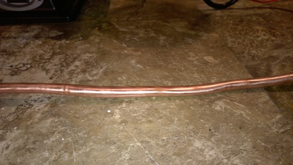


The air core inductor was made from 1/2″ copper tubing, as used in air condition and related applications. This was not easy to do. The trick to bend the tube without collapsing the hollow structure is to fill the copper tube with water, and then freeze it. After several hours in the fridge, you can now bend the tube, with no fear of ruining your expensive copper. After several efforts, I was left with a hand made copper ring ready for installation. After polishing and a lacquer coating, I thought it looked pretty good, considering all.


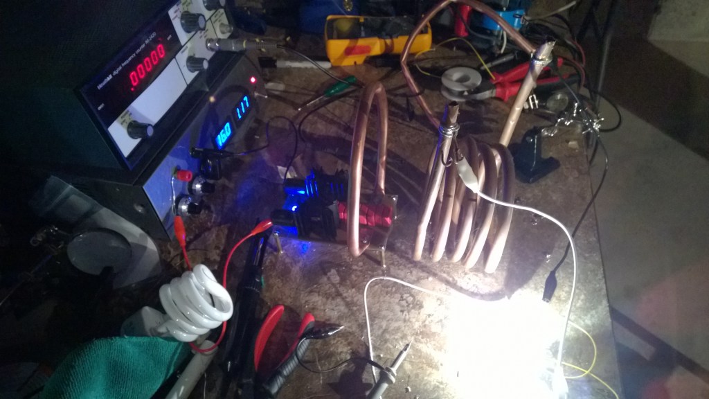
Here is the completed wireless energy transmitter. It was surprisingly difficult to find high current radio frequency inductors of such high value, but I found some in eBay that I thought looked fairly stylish. The tank capacitors are WIMA PP film capacitors, which are essential for proper circuit function. With the high peak currents of the tank, and the RF operation, few other capacitors would work. Forget about your Y5 ceramic!
The entire board was sprayed with lacquer to prevent corroding. Even after many years, it still looks this shiny!
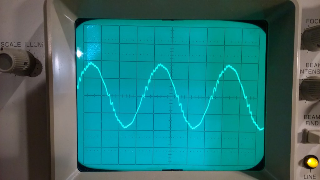


As you can see, pretty good results. I never made any serious attempts to measure the performance of the device, after all, it’s more a demo and toy than anything. As you can see, the tank waveforms have some switching ripple, and the whole thing oscillates around 1.2Mhz. In the demos, you can see my receivers are scrap pieces of copper, and I never actually built the receiver portion of this demo! I actually did bend an identical copper air core inductor, but by that time, I had lost interest in the project. Any future wireless energy transfer should be a microcontroller affair. In any case, I thought it was an attractive thing and it’s been sitting quite nicely on my bookshelf for several years now.
