
Tesla Coil Misc. (VTTC, SSTC)
VTTC, large SSTC, and others


Credit Wiki
Apologies for the spareness of this page, this page covers some of the Tesla Coils I built but have little documentation of.
Please look at my mini SSTC page for commentary on SSTC circuit design.
Vacuum Tube Tesla Coils
My interest in Tesla Coils was actually first directed towards the vacuum tube kind. I immediately fell in love with vacuum tubes – their retro look, the shiny glass bottle of metals. I was inspired to build one when I first learned about them through Steve Ward’s site – a fantastic resource for all things high voltage, and I learned a lot about electronics in general from that site.
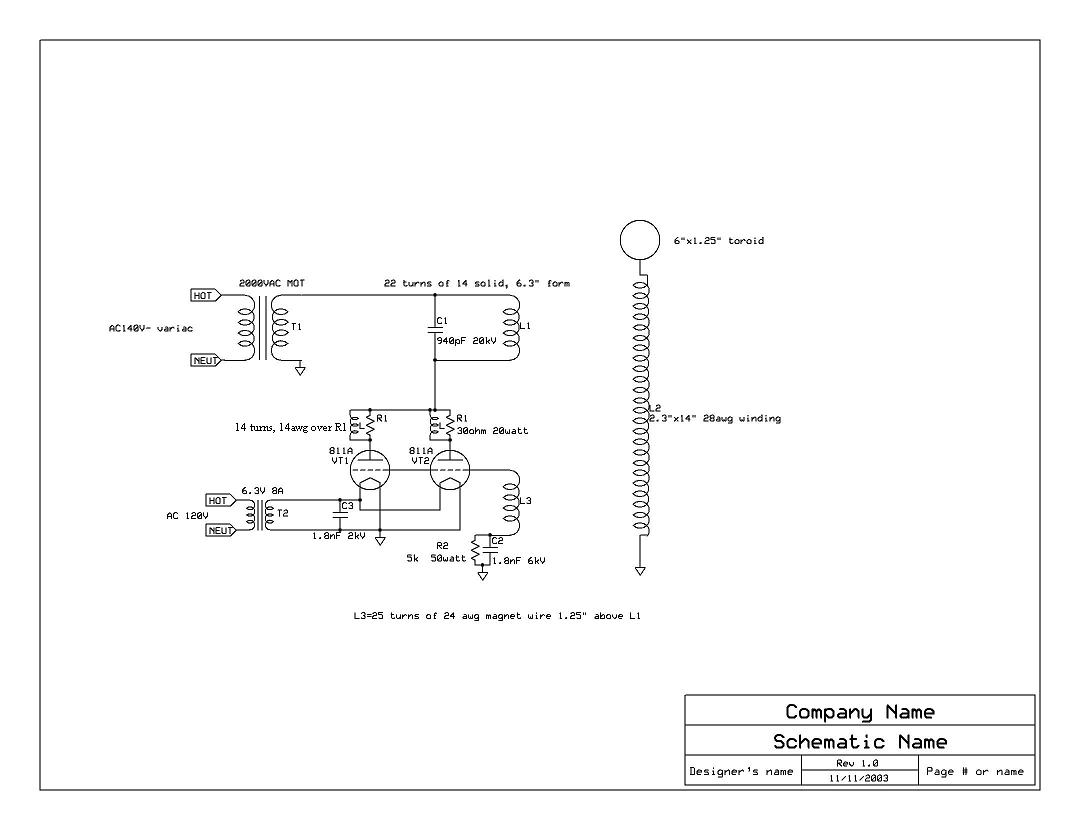
Remarks on Circuit
The vacuum tube tesla coil is simply a class C Armstrong oscillator. The tank capacitor and the inductor form the tuned circuit that drives the secondary at resonance. Feedback is obtained using the tickler coil, which is wrapped above the primary for magnetic coupling and must be adjusted for optimal performance. You can see the grid leak resistor (bias resistor) and the high frequency bypass capacitor connecting the tickler to ground. It is class C because the tube is biased to conduct less than 50% of the input signal, with high distortion as a result. Typical condition values are 80-120*. The output is a series of distorted pulses which are reshaped by the tuning circuit of the LC tank. This is commonly used in RF amplifiers of a single output frequency and efficiency is >70% optimally.
https://www.stevehv.4hv.org/VTTCfaq.htm
I couldn’t afford 811A tubes, however, so I settled on a tube I could afford, the 803 tube. This is how I ended up learning about datasheets – since no one had ever build a tesla coil using an 803 – (or since, probably) I had to read the datasheet, compare it to an 811A, and try to figure out what modifications I should make to the circuit. The 803 tube is the second picture on this page.
This coil ended up working pretty well. Sorry, no pictures.

Later, I built another VTTC using the 4-400A tube, a monster of a transmitter tube rated for 1000W dissipation on the plate. Sorry, no pictures again.
Large SSTCs


I know now this is not a very good layout for a high power RF design. But, this is the remains of one of my early SSTCs – this particular component being the H-bridge. The MOSFETs screwed into the terminals for easy replacement. There was a reason I needed them to be easily replaceable.
I’ve wound three or four Tesla Coil secondaries over the years. You design them in the numerous tesla design programs on the internet, such as JavaTC. This one was first made for a VTTC, and later used for an SSTC. Apologies for the sloppy primary – it’s just a mockup. I believe this had a resonance frequency of 300kHz. The toriod is made from air ducting.
