
Induction Heater
ZVS Induction Heater

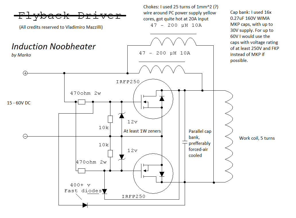
Credits to Marko
Unfortunately, this was something I built a long time ago, and I don’t have any pictures of it in operation anymore. By now, that’s a familiar story on this website. Just goes to show the importance of proper data management.
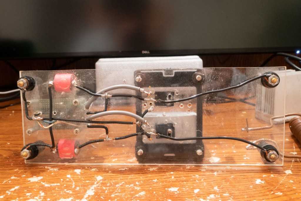
I was mildly interested in induction heating, but didn’t want to invest too much money in my little set up. I was also a little afraid of glowing hot metal, and didn’t have much practical use for it. So, I decided to build a modified ZVS driver for use in induction heating. As you can see, I decided to make it at least partially pleasing to the eye, and built it on a clear piece of acrylic. Luckily I never cracked it while drilling mounting holes.
Remarks on circuit
The ZVS driver is named because it exhibits Zero Voltage Switching, where the transistors switch when the tank is at zero voltage. When the circuit is first turned on one of the resistors will turn on – let’s assume the top transistor. The drain of the top transistor will be ground, and the gate of the bottom transistor will be at zero due to discharging through the ultrafast UF4007 diode. The circuit will conduct current up through the work coil. Because the work coil forms an LC resonance tank, the output is a sinewave. When the voltage at the bottom of the coil is zero, the top transistor gate will discharge and the process will repeat with the bottom transistor. Since switching and thus the linear region of the MOSFETs occur at zero crossing, very little power is dissipated other than the natural RdsON of the devices.
I use this same topology in my wireless energy transmitter (L)
The mockup picture that’s first on this page was taken about an hour before I wrote this, and so several years after the device was last in operation. While that copper coil on the right was my work coil, I think, it’s missing the huge bank of WIMA capacitors I used for the tank capacitor.

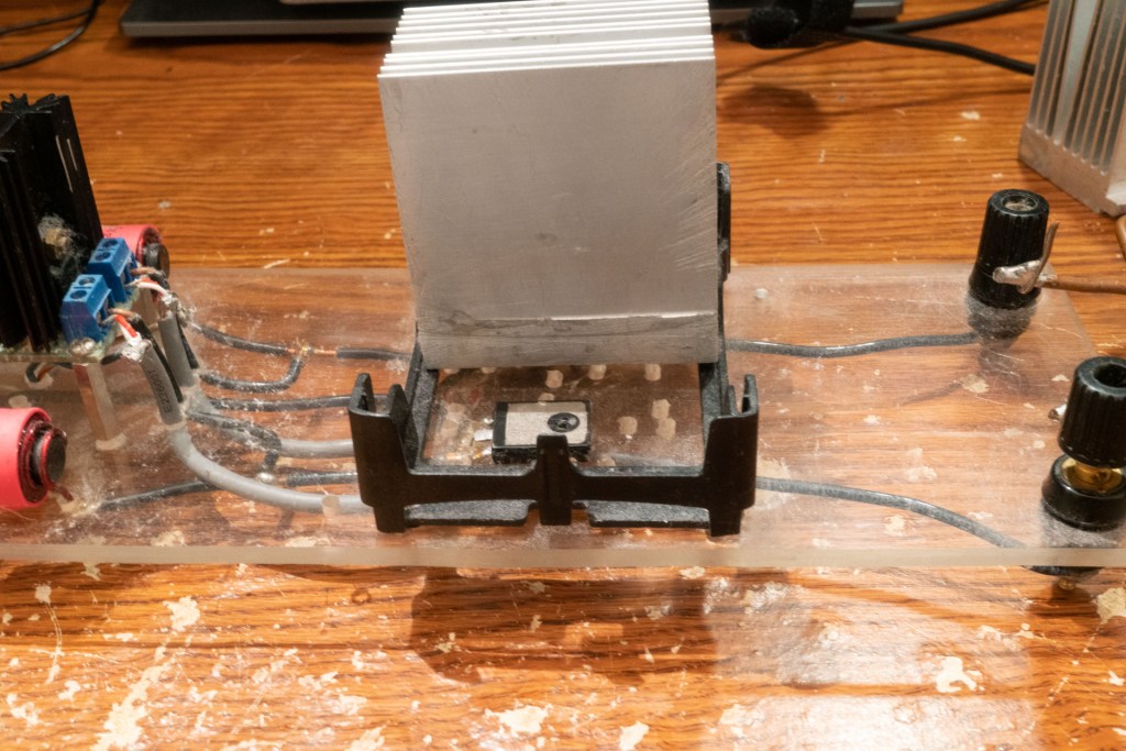

As you can see, my cooling solution for the MOSFETs was a CPU heatsink. You won’t believe the effort it took to saw that heatsink in half, using only hand tools. It was almost as bad as when I removed the secondary from a microwave oven transformer! (that’s another story) It’s dusty now, but it looked pretty good when i finished it back then
Apologies for having no pictures of it in operation, again, I never thought I’d show anybody other than myself and my parents at the time.
