Linear Power Supply


LM723 + 2N3055 Pass Transistor Linear Power Supply: 0-40V DC 0-20A
I needed a suitable low voltage power supply for projects, and I was getting disillusioned with the prospects of nabbing a suitable one on eBay. For one thing, they were all all at least 40lbs for anything around the power levels I was looking for, (I was working with induction heating at the time and was looking for 500W+) while anything that was even near reasonable to ship was a puny 0-12V 0-5A job. Even a cheap Chinese power supply was out of my price league, with a dual tracking 0-40V 0-10A supply going for about $300. So, I decided to make my own.
Remarks on Circuit
The LM723 and the 2N3055 are some old school components that have been in production since the 1970s. While the 723 is rather long in the tooth and has poor current control, and the 2N3055 has 1960s levels of gain, I didn’t think there was a real need to go for high tech in my linear power supply. All it needed was a huge heatsink, some heavy duty current buses, and a presentable case. The schematic is taken from another website, but the design of a 723 linear supply is pretty straightforward. The only trick might be the balancing resistors of the four 3055 NPNs, which requires high dissipation wire wound resistors. The LM723 takes feedback on pin 4 through the voltage divider, and the BD139 drive the bases of the NPNs.


As you can see, I took heat dissipation pretty seriously in my design. I bought an old audio amplifier heatsink on eBay, which had the TO-3 package mounts. It’s nice working with these old TO-3 packages, not so nice to find mounting gear for them these days. Yes, there were mica insulators between the TO-3s and the heatsink, so the chassis was not at potential. The above picture shows the assembly in testing, while the lower pictures shows it installed inside my case. For filtering there was 8000uF of electrolytes, and the rectifier was mounted directly to the heatsink. It was one of those square packages with the screw hole for easy mounting. I used 12 gauge solid core wire for all high current buses, and as you can see I directly soldered to the packages of the transistors. While robust, this proved to be a terrible pain when I blew out my first set of transistors during testing. This explains the more mangled state of the buses in the final mounted picture.

Here is the simple circuit board for the LM723 and jellybeans. The BD139 needs no heatsink. As you can see, pretty old fashioned construction. The terminal strips I use to mount the filtering capacitor for the logic supply are something I learned from my antique radio restoration. I’ve also always liked the vertical mounting of axial resistors as seen in some older equipment and inexpensive consumer equipment. Unfortunately, there is the risk of the exposed leads touching something they aren’t supposed to, which I think was the downfall of my initial install of the 2N3055 transistors. I’m not really proud of the way this looks – really should have used at least a screw terminal for the connecting wires – but, it works and I never expected to have to show it to anyone. All my vanity went into how it looked on the outside, you see.

Here is a full view of the inside of my linear power supply. The case is an old PA amplifier that I stripped out, modified, and painted with hammered paint. I really like the stuff, works wonders on any surface. The transformer is painted with the stuff too, I scrapped it from some gear years ago. It had a 5v winding that I used for the logic, and a 40v winding for the main supply. It isn’t really rated for 500W, in all honesty, but I had it, it was free, and it fit in the chassis.
One of the less talked about parts of building homebrew items is buying items that all fit together. As you can see, that heatsink barely fits inside the case. I believe I had to dremel off some standoffs to make it fit anyway. Buying things on eBay is the hunt of finding items for cheap that’ll work in your design, trying to figure out dimensions, and messaging sellers who are on the most part helpful, though there is the rare bad apple.

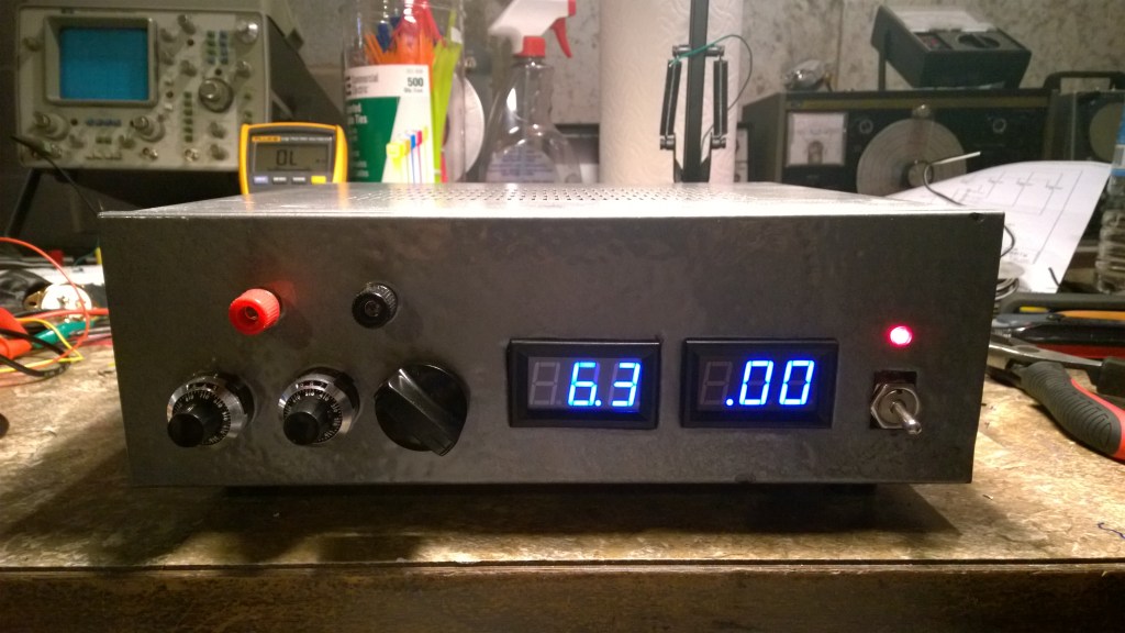
Here is the front panel of the power supply, in all of its spray painted and Dremel glory. The cheap digital voltmeter and current meter are more or less mounted straight, and the mounts I cut are fairly well fitting. The million coats of thick paint helped cover up the misshapes I had. The three knobs I put on the left hand side of the device are voltage, current fine, and current rough. As you can probably guess, voltage and current fine are ten turn pots, nice Bourns manufacture. Current rough is R8 in the schematic and is a 5k 1/4W single turn pot. The knob I believe is from a 1960s EICO oscilloscope.
The paint job was about five layers of hammered paint. After years of experience of spray painting my projects, I think I got pretty good at it by this point. The paint is as solid as a rock; to harden it I placed it in my oven at 170F for about two hours. Great tip for anyone wanting to prevent scratches.
Placing the output terminals directly above the controls was perhaps not the most user friendly or safe design choice, however I strongly maintain from an aesthetic point of view that it looked most balanced placed there. I also started drilling before I started planning.