
Mini SSTC (Tesla Coil)

Credit Gao G. 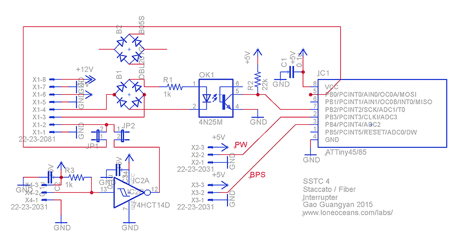
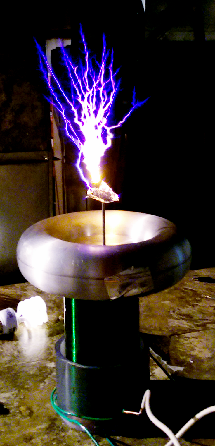
This is the latest Tesla Coil I built, a small eight inch tall coil with sparks roughly the same length. I was hoping for lengths of 16+, but one of the windings of the secondary coil had its insulation fail, ending the coil’s life prematurely. I’ve been building tesla coils for many years now, though I’ve mainly focused on vacuum tube (VTTC) and solid state (SSTC) types. Unfortunately, I’ve lost the documentation for most of those projects, leaving this one as the sole tesla coil for which I have full documentation for.
Remarks on circuit

This is a diagram of a classic SSTC I made for a science fair some years back. It specifically describes an SSTC with audio modulation, showing both FM and PWM types. The tesla coil I’m describing here lacks that feature, but the rest still applies.
To briefly summarize the device operation, first assume the tesla coil is already in operation. In practice, the random parasitic oscillations of the circuit will start up the coil, though most “coilers,” as the community calls itself, will invoke the use of an interrupter, which will kick start operation reliably. Positive feedback from the secondary coil is sampled using its base current with a current transformer. Early tesla coil designs (circa ~2000s) used an antenna, but the risk of an antenna strike blowing out the whole input stage was great. This feedback is squared using a schmitt trigger, which is then used to drive the gate drivers for the H bridge. Instead of a motor being the H-bridge load, it’s the tesla coil primary, which couples the energy to the secondary. Acting as an air core transformer with secondary resonance, high voltage is produced. The evolution of the SSTC, the DRSSTC, uses a tuned primary resonant with the secondary, but I’ve yet to build one of those.
This particular circuit adds some details to implement an interrupter and zero volts crossing in the interruption. The feedback is fed through two schmitt triggers into the interrupt of the gate drivers, turning on and off the bridge transistors. Normally, this is at 100% duty cycle, or continuous wave. We can control the duty cycle using an interrupter, which is implemented in the 2nd schematic and is a simple microcontroller. The interrupter can be used for audio modulation via PWM if desired. Anyway, the signal gets inverted by the schmitt trigger IC3A and is fed into a D latch that acts as a zero volts crossing enforcer, as it can only change state at the rising edge of the clock, which is wired to the interrupts. The inverted Q’ of the D latch pulls down the enables of drive chip, enforcing a variable duty cycle. We would like to enforce zero volts crossing mostly to reduce stress on the drive transistors. This is more important in a DRSSTC, but is good design practice. The rest is pretty straightforward.


I know I don’t have any pictures, but this wasn’t my first SSTC. I’ve built several over the years. This time around, I was interested in designing a PCB for one. However, I found someone selling spare copies of their PCB design on the internet, and I liked their design a lot. SSTC topology is fairly straightforward, and design choices are mostly based on material restrictions. This design uses all off the shelf parts, including the gate driver transformers, which I have had frustration and drudgery winding my own over the years. A good resource for building your own is on the 4HV wiki. He also designed his own discrete gate drivers, with N-chan and P-chan MOSFETs in totem pole configurations. Even after all the zener overvoltage protection in the world, every tesla coil builder goes through piles of money in UCC37322/1 gate drivers. Ridiculously expensive chips, and this solution used maybe $3 of parts. So I bought the PCB from him, studied the schematic, ordered the parts, (which I had to pick out myself) and constructed it.
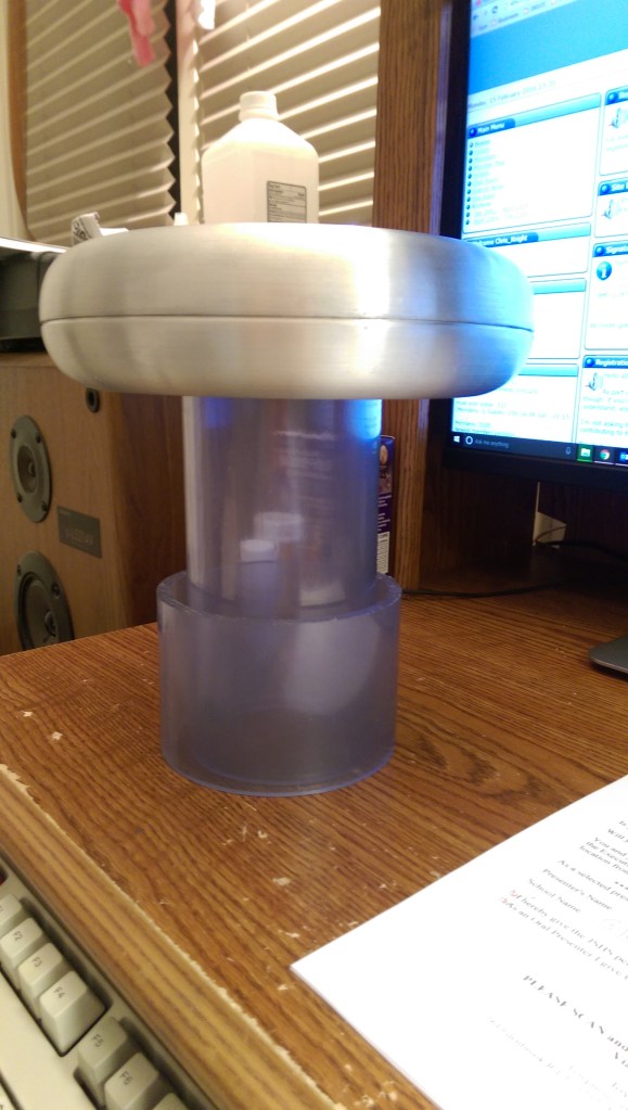

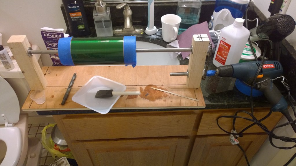
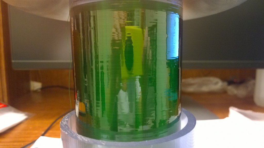
Here’s the process of winding the secondary. Basically, after designing your coil in your favorite program, (I like JavaTC) turn on the tv, get some magnet wire and a PVC pipe, and start wrapping. You might imagine this process tedious – and it is. Anyway, after finishing winding your coil, you have to coat it. I’ve used lacquer, but it requires many coats, and is thin. I had heard of this new pour-on poly stuff, and I decided to give that a try. As you can see in the second and third picture, I built myself a sort of rotisserie thing to continuously turn the coil to ensure an even coating. As you can see, the results were quite nice. A pity the thing died so soon. It will be a while before I’ve built up the required patience to do it all over again – but writing this has done tremendous work in doing so.


You can see me gradually dial in the primary winding. Since it’s not resonant with the secondary, the number and location of primary turns solely determines coupling, the challenge being finding the sweet spot. Over coupling can lead to arcs between the secondary and the primary. Which is what happened eventually. Glad I still have these photos though.
