
Plasma Speaker(s)
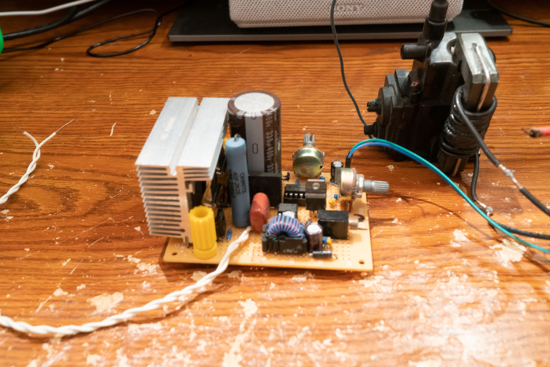
One of the half dozen or so I’ve built

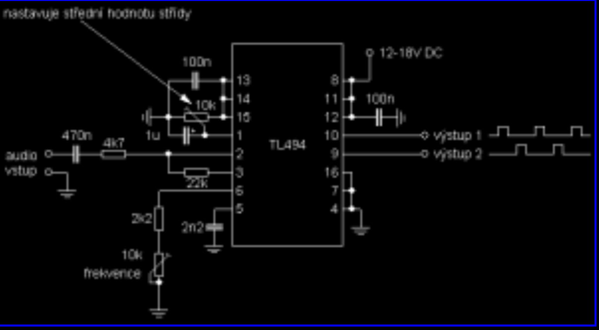
Credit Jan 
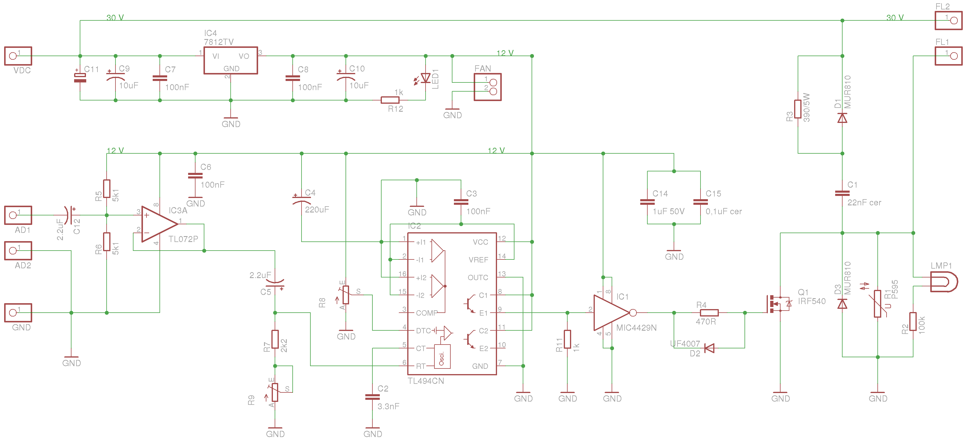
Credit Jan
As a kid I often took apart things to see how they worked. Later, I tried to put them back together. The first time I tried to build an electronics project from scratch, however, was in sixth grade, when I saw this article on Indestructibles:
https://www.instructables.com/id/Build-A-Plasma-Speaker/
Remarks on Circuit
For those not in the know, a Plasma Speaker is a audio modulated high voltage arc, which uses the atmospheric gas ionized by the arc as the diaphragm of a massless speaker. The typical topology is a PWM modulated flyback transformer – which is the high frequency ferrite transformer used to generate the high voltage in a CRT television. When I read that article, I immediately knew I had to build one of my own. So I did. Over the years I’ve built about a half dozen plasma speakers, all of them slightly different and all of them well performing. Unfortunately, I’ve lost the video and images of most of these devices, and over the years cannibalized them for parts, so I have little evidence of most of them. The one pictured above was a quick project I made in a night or so, and which worked “just ok.” On this page I’ll give a brief summary of the different topologies I used and some of the remaining pictures I have.

This is a terrible design and I wouldn’t wish it on anybody. While this was the original schematic I saw on Indestructibles, I never built it.
To clarify – the PWM section formed by the TL494 is a classic circuit that was popularized by Steve Connor of scopeboy.com – and I’ve continued to use it for PWM modulation all these years. That’s fantastic. But the single ended MOSFET driver is horrible and will quickly destroy any transistor. “Requires a large heatsink” – read between the lines!
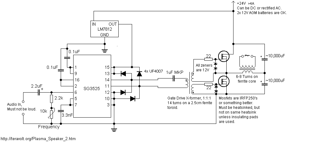
Now we’re getting somewhere. This is the same PWM TL494 driver section, (SG3525 being near equivalent) but now we have a gate drive transformer (GDT) and half bridge section. This works just fine – I found no difference between half bridge and H-bridge performance. However, with larger MOSFETs and IGBTs, the poor TTL TL494 can’t supply nearly enough current, and will burn off. A gate driver is critical for reliable performance.
http://thedatastream.4hv.org/gdt_index.htm
Just a quick word on GDTs – they are one of the most mysterious parts of any MOSFET driver. It’s usually best to wind your own, since this application is pretty niche in the consumer electronics world, and you’ll usually get better performance too. Attached is a guide to winding your own GDT – but basically you buy random ferrite cores on eBay, wind a trifiler winding, and test and see which one works best. How many windings you wind is again down to art, most of the time.
Just a quick detour before we end up on my favorite design – this uses the bad single ended output, but implements FM modulation of the PWM signal. I thought this was really interesting and had high hopes this might be superior to PWM. I built the circuit and tried it with my output stages at the time – and no real difference. It’s possibly better, but not significantly so.
This is one of my surviving circuit boards of a PWM driver. At some point I built a modular plasma speaker with BNC shielded cables between the PWM generation and driver stages, hoping for less interference. It didn’t make much of a difference. This is one of the first circuit boards I made.
Apologies for the potato quality resolution on this picture – the website I got this from no longer exists and I had to use the wayback machine to grab this image.
This is the final flyback driver I settled on. It has a number of advantages. The UCC gate driver and IRF540 that drive the GDT result in a really high quality gate drive signal that’s strong, as it’s 15v vs 5v of a TTL signal. This output stage with in phase transistors is unusual, and I’m not sure what it’s called, but it’s basically two single ended stages with the flyback primary in between. This produces the highest quality audio of any of the stages I’ve discussed previously. The catch diodes recycle the kickback of the primary to the filter cap, which prevents nasty things happening to our transistors.
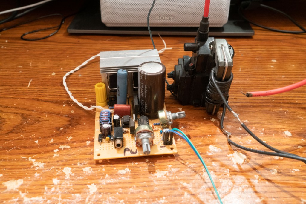
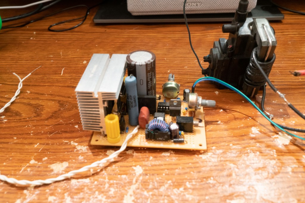
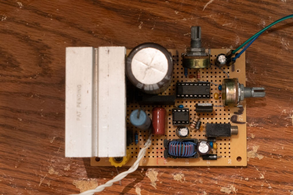
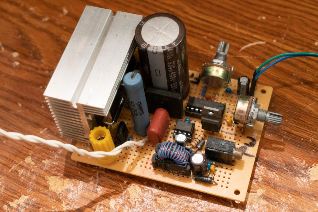

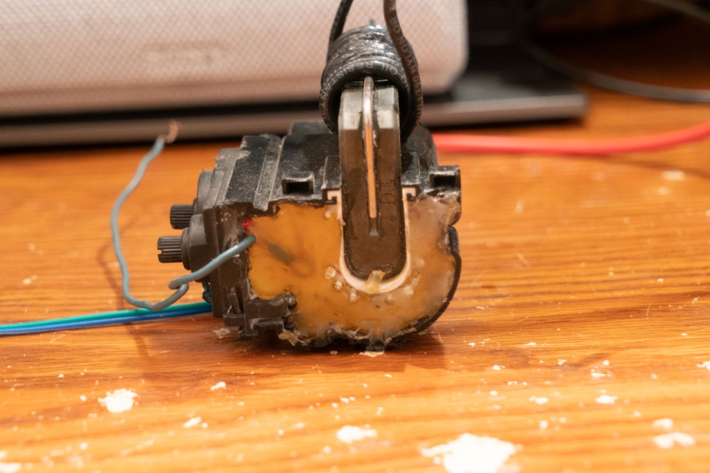
hot glue to prevent arcing
Here’s the scrap parts flyback driver I built. I apologize for the terrible construction – it was made in a night and with only parts I had laying around. the catch diodes I scrounged also failed, taking out the transistors with them shortly after building, so there’s that too. Not my best work but the only plasma speaker example I still have.
