
RCA T8-18
I had the hobby of antique radio collecting for about four or five years, starting in middle school. I was never very good at the woodworking or painting aspect, (though I got fairly adept with a spray can) but found the electronics bit very interesting. Combined with my urge to produce perfectly clean examples, I got into the habit of completely disassembling my radio chassises and putting them back together. This helped push along my study of radio engineering in the vaccum tube tradition enormously – as oftentimes the schematic was error ridden and I had to discern what made sense from an electrical viewpoint.
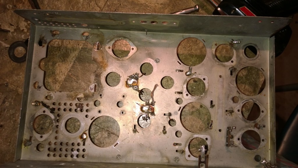
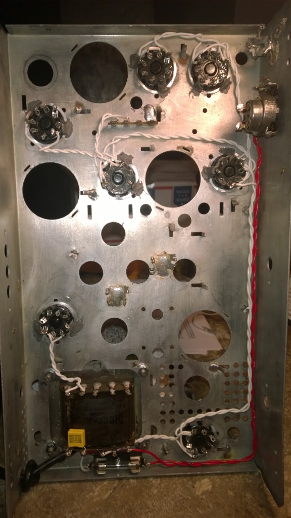
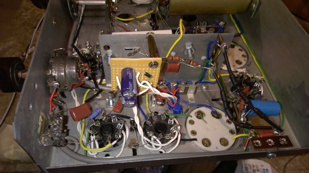
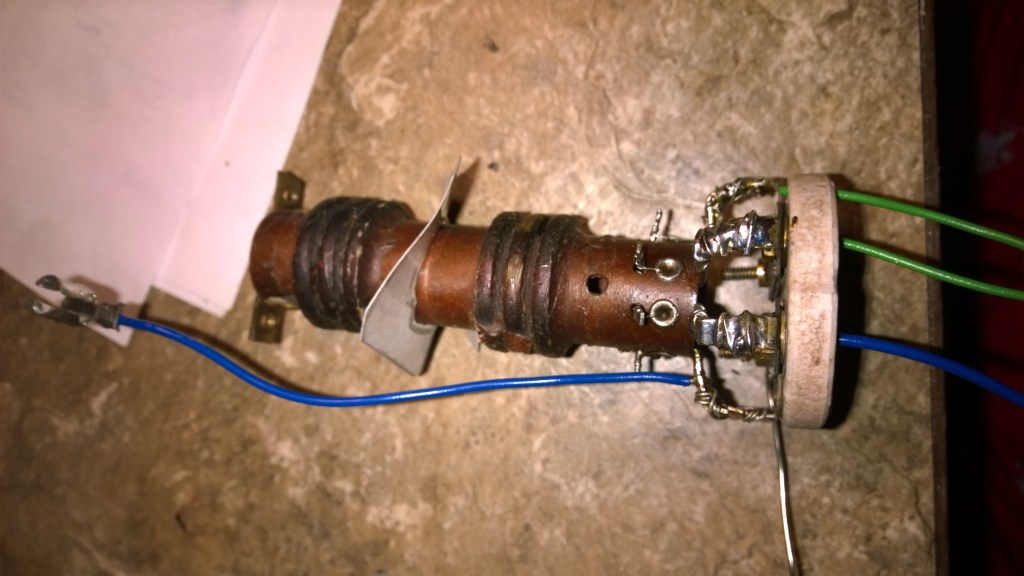
To briefly summarize what restoring an antique radio entail, all the components that degrade over time have to be replaced. Contrary to popular knowledge, vacuum tubes generally do not degrade over time, with exception for early gas filled tubes like the helium BH tube. The electrolyte and paper (plastic dielectrics having not been developed) capacitors must be replaced universally, while the resistors at times will have drifted severely. Infrequently, transformers can have their windings break down, due to the acidity of the potting material, in addition to the hundreds of little breakdowns and troubles that the radio restorer learns about through their experience. For example, this radio, like a great many of the 1930s designs, has several candohms. (ohms in a can) This chassis mount wirewound resistor is designed in not a very good way.

As you can probably guess, the flat part of the resistor is a rectangle of wrapped wire, insulated with thin wax paper, and canned tightly with a wrap of sheet metal. Not only do the wires all eventually fail, the insulation also has a tendency to fail. A reminder that the candohm frame is bolted to the chassis, and the chassis is almost universally the negative in tube circuits. The Candohm had the benefit of having a high wattage rating for cheap, since the chassis helped dissipate heat. So, it was used in the power supply section of radios. Not surprisingly, many of the radios with candohms are found with blown transformers.
Remarks on Circuit
The basic radio works on the principle of the superheterodyne circuit, which was invented by Edwin Armstrong in 1917, who also invented the regenerative receiver and FM modulation. Tragically he would commit suicide after a failed court battle with RCA over his FM patents.
The circuit works on the principle of heterodyning, where two frequencies will product multiples of their frequencies: f1+f2 and f1-f2. So, by having a local oscillator that is always a fixed frequency above the receiving signal, e.g. 100kHz receiving signal and 175kHz local oscillator, one can extract an intermediate frequency of 75kHz. So, demodulation can be done at a fixed frequency and one can have a fixed frequency bandpass filter at a fixed frequency. This also allows for components of lower frequency in these sections, as the IF frequency is lower than the RF signal frequency. This was the major issue that Armstrong faced, as circuits of the day had great difficulty in operating above 500kHz. (1910s) Demodulation is simple DC rectification of the IF signal.
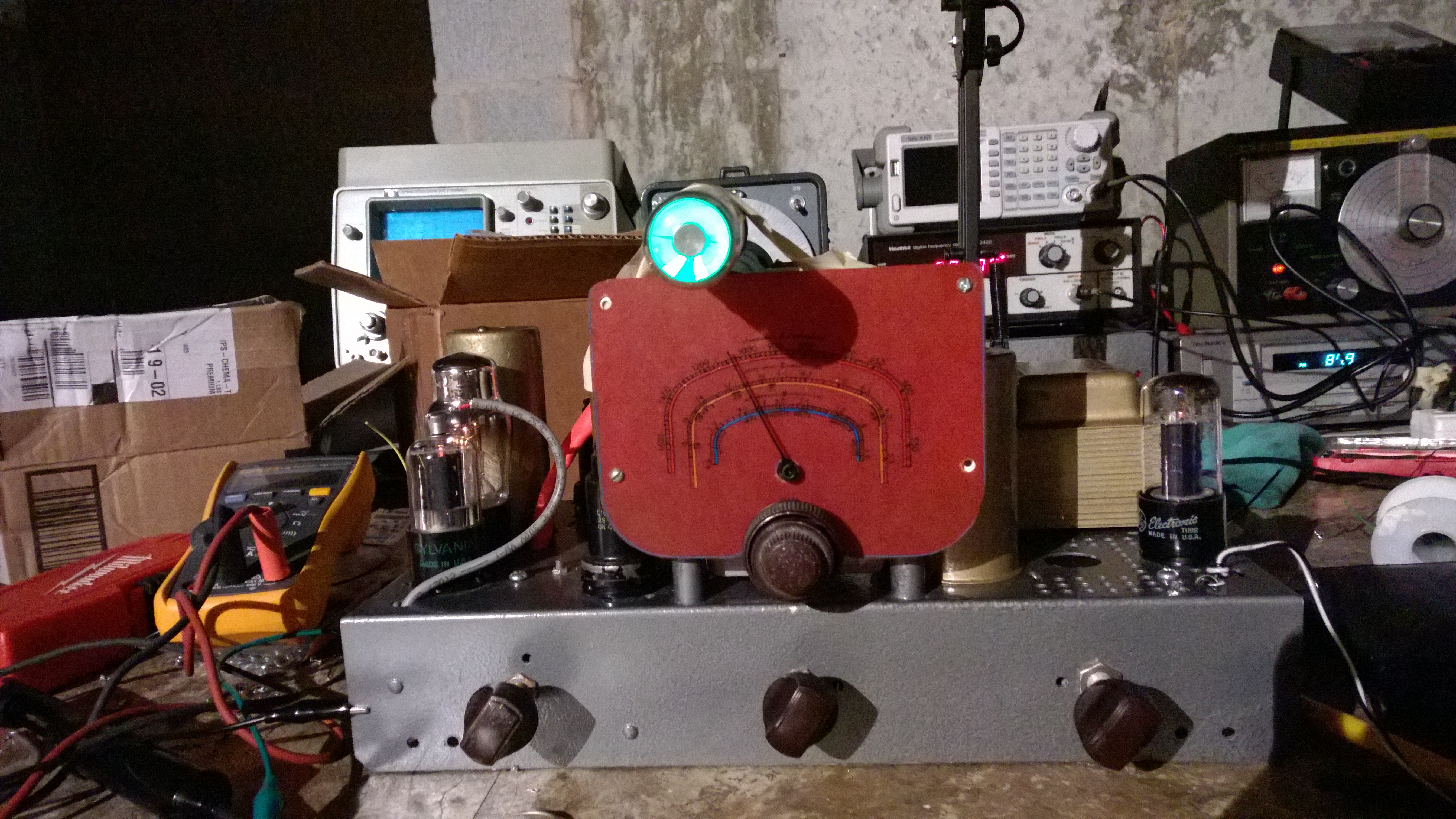
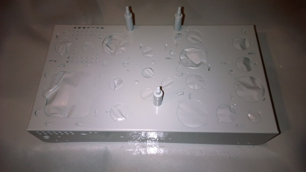
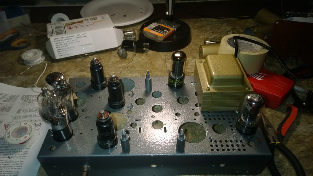
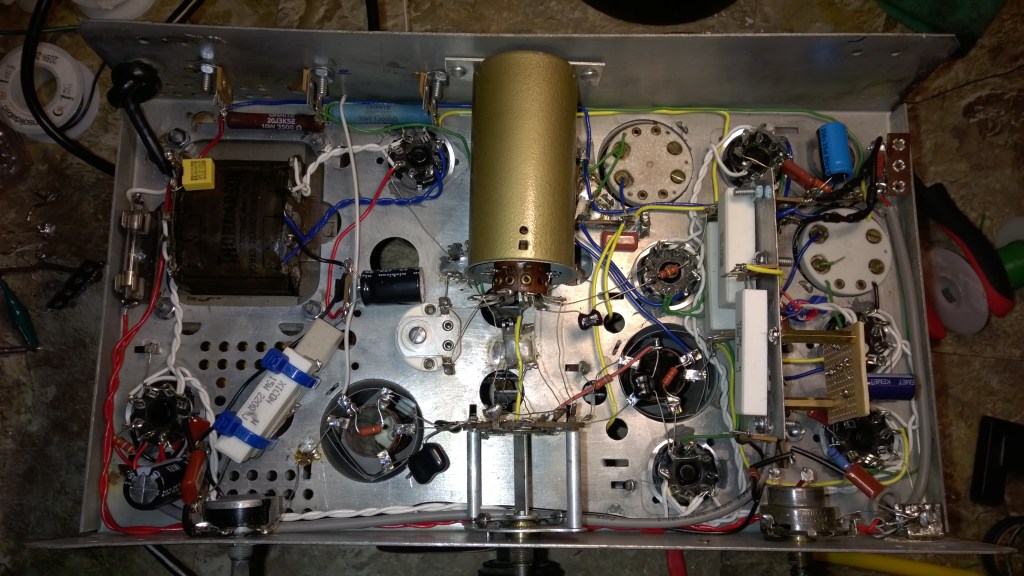
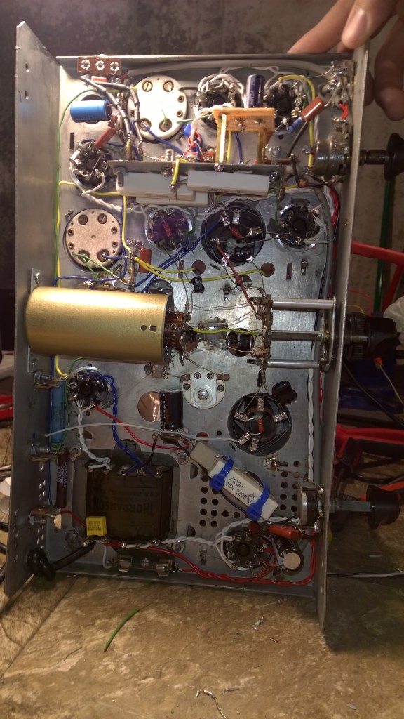
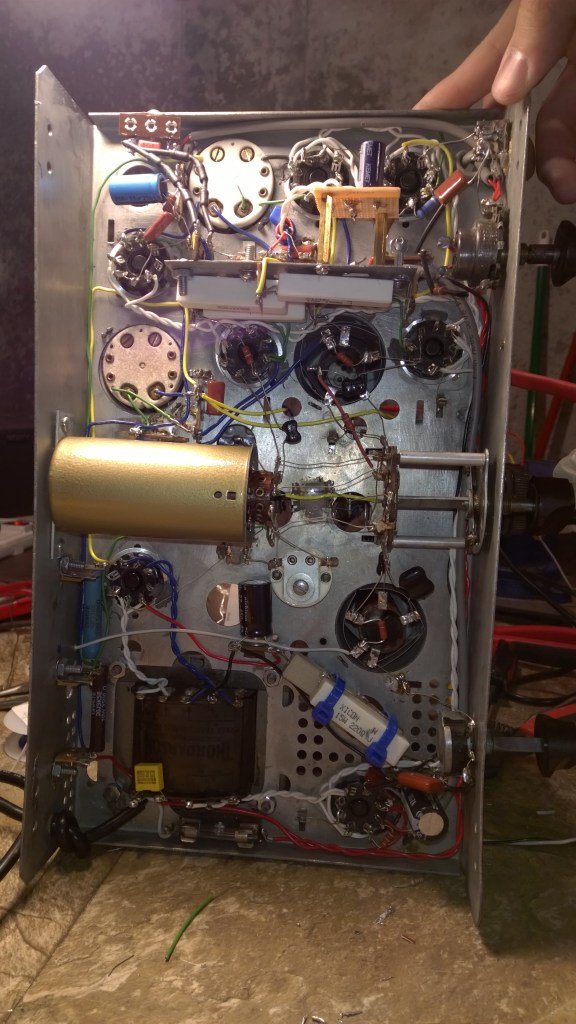
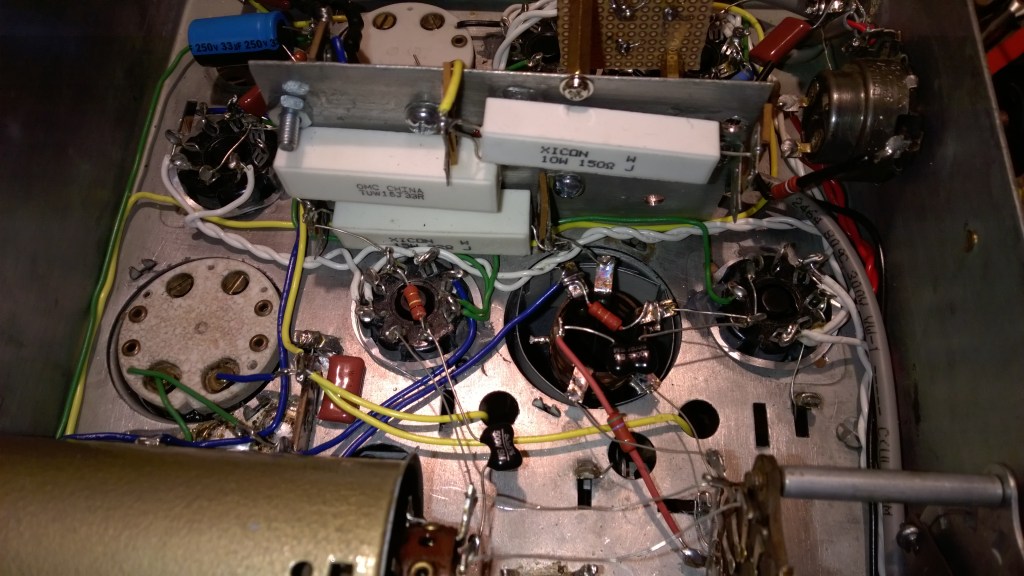
This RCA T8-18 was one of the radios which I found in very dirty condition and decided to completely refurbish. It is the 2nd year of eye tubes, which started in 1936. It is also the first year of metal tubes, and this set would have originally featured all metal tubes. It is an eight tube radio with a six tube high frequency section, the extra tubes being the eye tube and an audio driver tube for the 6F6, the predecessor to the more famous 6V6. The LC tank, which is the bandpass filter for station selection, uses a variable air capacitor. This variable air capacitor is mechanically linked to another variable air capacitor for the local oscillator. The RF tubes include the 6K7 as a radio frequency amplifier, the 1st Det. & Oscillator 6A8 as the mixer and local oscillator tube, and the 6H6 for demodulation and automatic volume control.
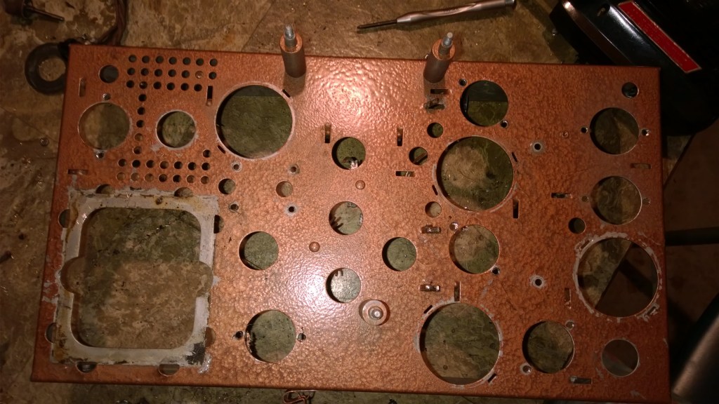
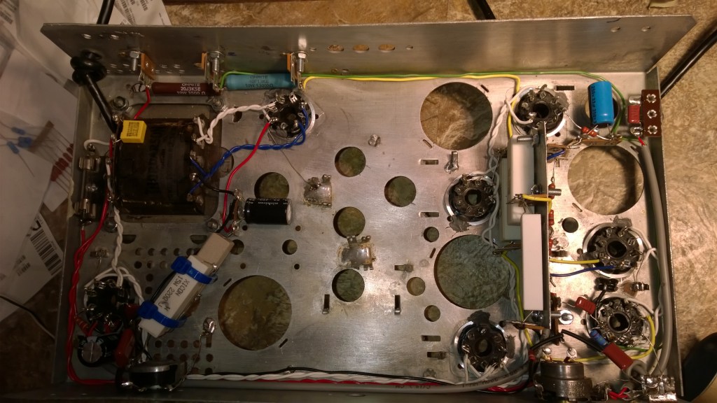
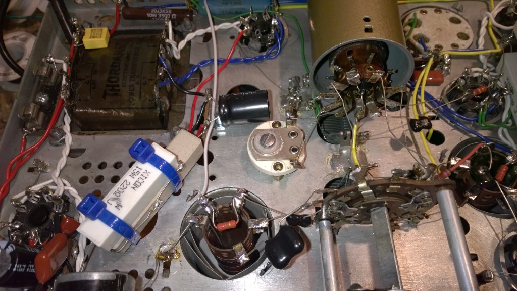
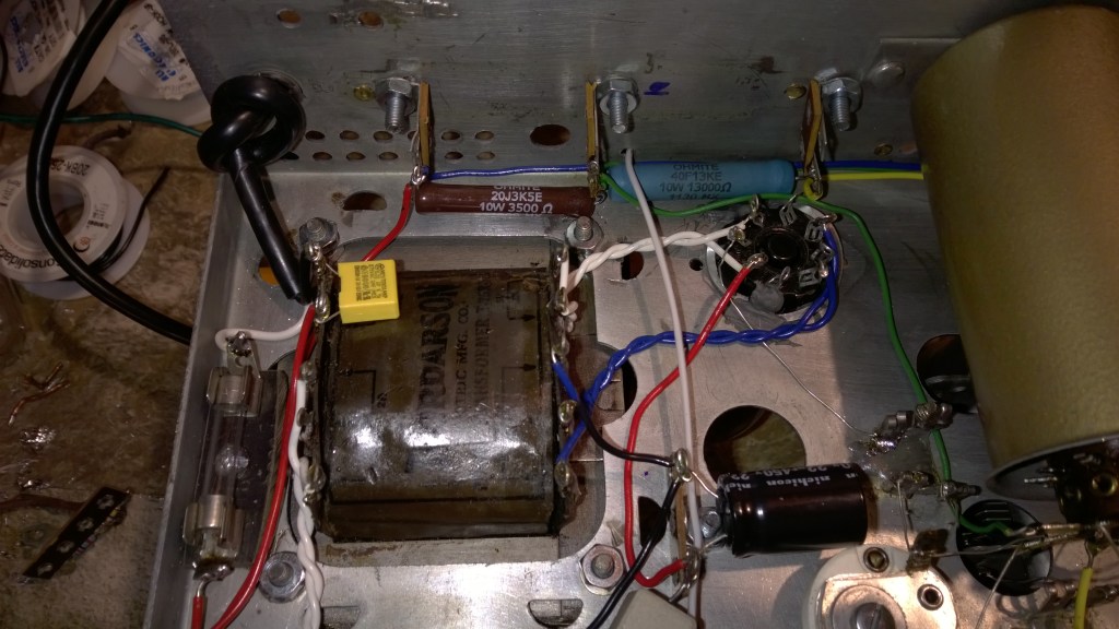
Some of the things I did were replace a burned out transformer, clean everything and replace all the cracked rubber wiring, replace all capacitors and resistors, and replace the tube sockets. It’s better than new, since originally they wouldn’t have painted them.


Can’t post a video on a website, but reception is excellent and I’m very happy with how this turned out.
